Using the Plane Tool to Make Contacts Between Adjacent Implants Ideal
Creating crown counters between adjacent implant crowns can be tricky to get just right. If too broad, it can interfere with seating… if not broad enough can promote food impaction between the embrasure spaces.
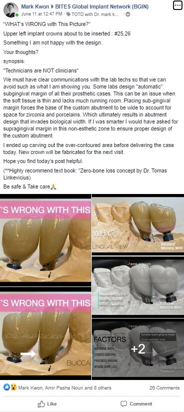
This post was inspired by Dr. Mark Kwon’s post in BITES Facebook group because he brought up a very important clinical factor – contacts between adjacent implant crowns. I encourage you to check out the Facebook group, it’s a very nice resource for learning.
We strive to look for that ideal balance between crowns that “drop right in” and those that “need a bit of adjustment but fits our technical ideal.” The challenge is that when using standard stock healing abutments, to get implants crowns that drop right in, often it leads to strange subgingival contours. Thankfully, the tissues between an implant and adjacent tooth tend to fill in, the tissues between adjacent implants typically remain flat over time. Getting that ideal crown contour that our laboratories strive for often requires anesthesia and sometimes tissue curettage to seat an implant crown. Not a great experience for our patients.
I was introduced to the “plane tool” by messing around with software to figure out how I can better my crown contours. The idea is that you can, with a click of the mouse, create ideal inter-implant crown contours (or natural crowns) in a matter of a few moments.
I have a patent who ended up losing teeth #29 and 30. We placed Hiossen implants and the OneGuide system using guided surgery to get them in ideal positions. After integration, we brought the patient back in for final impressions. Typically I like to adjust adjacent tooth contacts to get them more broad. We were able to adjust a bit but the patient didn’t want me to adjust an excessive amount. I let him know that he may eventually need a crown on tooth #31 due to non-ideal contours.
Some clinicians advocate for splinting adjacent implant crowns to minimize food impaction, although we get many patients who just want implant teeth that feel like natural teeth and can be flossed between them. I do agree with the option of splinting in this case, however, I mentioned it to the patient and he said he would like them individual crowns, if possible.
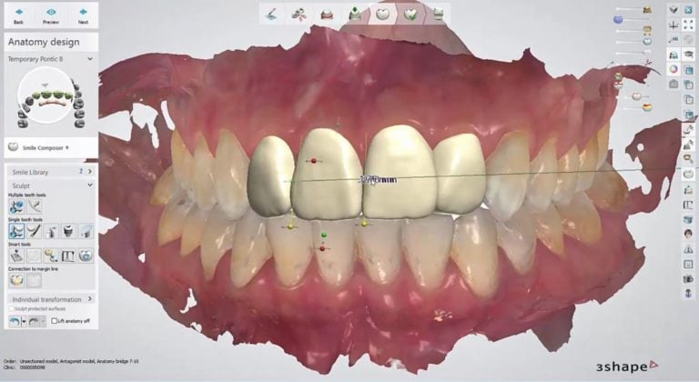
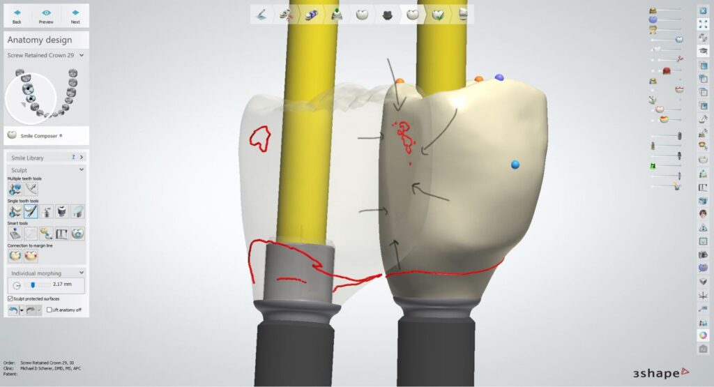
In 3Shape Dental System software, I designed the crowns. To use the plane tool properly, I first started out with essentially a completed design of the two crowns, note the less than ideal inter-implant contours.
Note: this case is a fairly straight forward one where my typical protocol is to ensure that I’m compressing the tissues slightly in adjacent tooth-implant spaces, like between #28-29 and #30-31. I did advise the patient that we should get good closure of the space between #28-29 with simple tissue pressure but we may need to replace the crown on tooth #31 since that contour simply was quite a bit off. If I replace that tooth, I will have an ideal distal surface on tooth #30 to close the embrasure space.
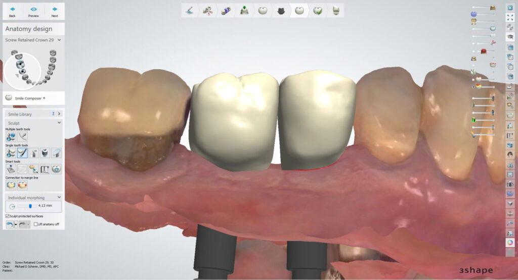
I then used the built-in morphing tool to bulk-out the interproximal contours. After bulking out the contours, the crowns typically have an overlap between them.I could mill the case just like this but it would need extensive adjustments in the laboratory to get the two crowns to seat properly. This is where the plane cut tool comes in handy.
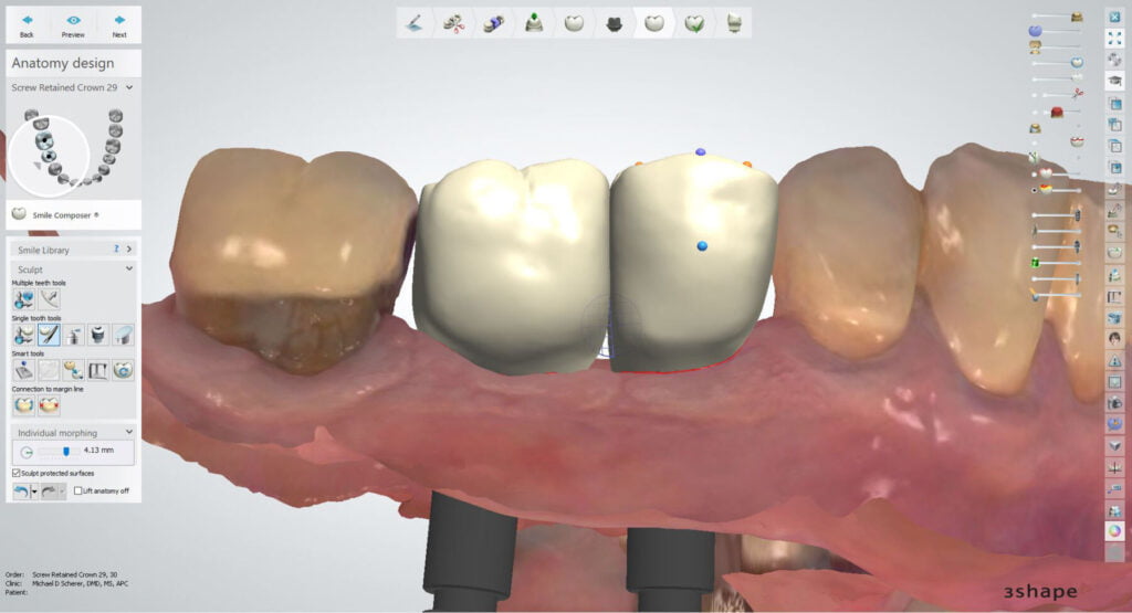
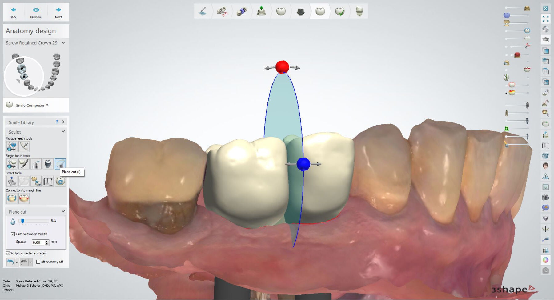
I select the “plane cut” tool and it creates a virtual disc with orbs I can move around. It’s essentially like taking a disc and slicing between a wax-up of a case and the red and blue orbs allow me to control the angle and the mesial-distal position of the slice.

The idea of the plane cut tool is to slice the crown contours so they are evenly touching in a very thin contact surface with no overlap. Almost like in Seinfeld when Kramer bought his own meat slicer and wanted to slice the meat so thin he could see through it!
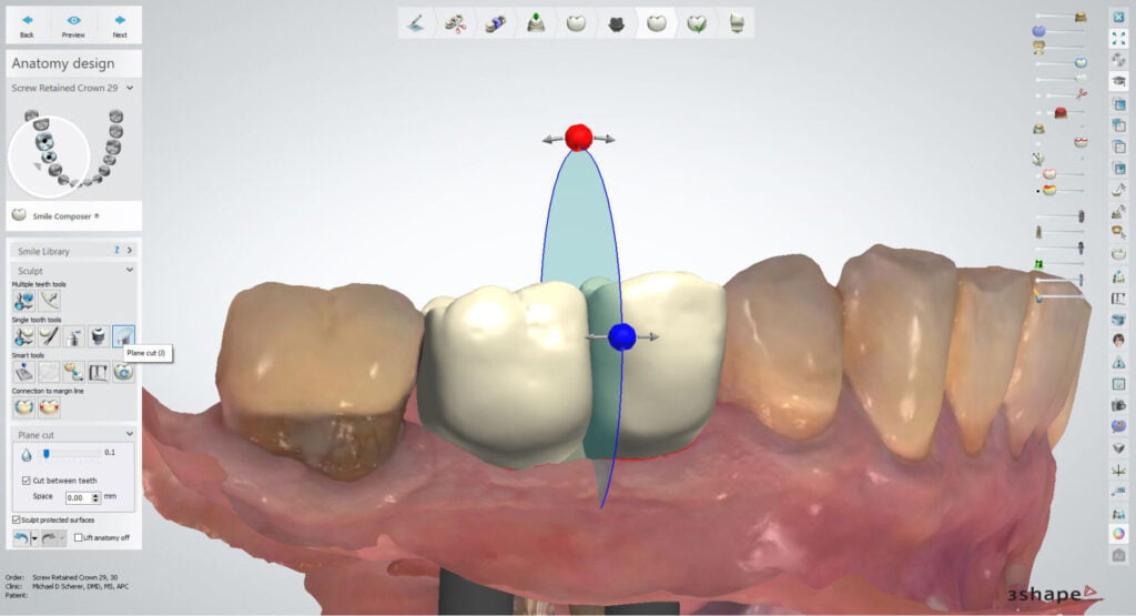
After using the plane cut tool, I can view the adjacent teeth in 2D cross section to ensure the contact point between the two crowns isn’t a “point” but a “surface.”
Using the tool gives me an ideal interproximal surface and one that will lead to minimal food impaction between the adjacent implant crowns.
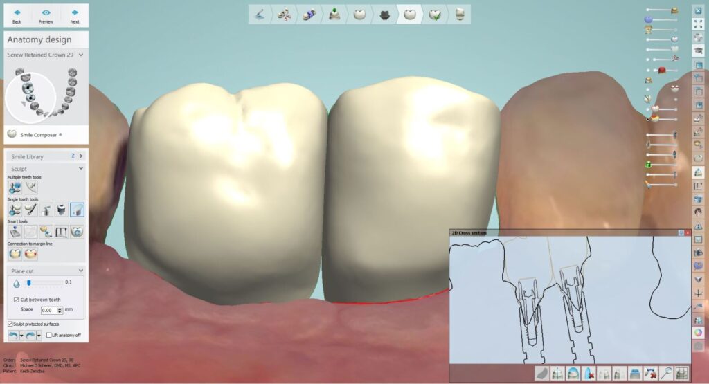
The plane cut tool creates a very long inter-implant surface as shown in this photo below. I drew arrows to the area indicating a super flat adjacent crown contour.
Let’s go ahead and take a look at a video of trying the crowns on the printed model immediately after milling (prior to any adjustments).
This case illustrates how we can approach using digital software to help assist us in the analog world. There is no 100% digital dentistry office as there will always be a component of using our hands and they are analog!! The key here is using the software tools to ensure that I minimize the number of adjustments needed in both the laboratory and clinical chair!
Interested in learning more about CBCT, implant planning, 3D printing, and some amazing step-by-step guided surgery protocols in your office and/or laboratory? Check out our innovative step-by-step online digital dentistry course at www.LearnDental3D.com

Dr. Michael Scherer, DMD, MS
Dr. Michael Scherer is an Assistant Clinical Professor at Loma Linda University, a Clinical Instructor at University of Nevada – Las Vegas. He is a fellow of the American College of Prosthodontists, has published articles, books, and in-person and online courses related to implant dentistry, clinical prosthodontics, and digital technology with a special emphasis on full-arch reconstruction.

